Amberina Case
Some Further Examples
The rich collection of the Clements Library holds many more maps and fortification plans than it is possible to display in the limited capacity of our exhibit cases. Here are a few more examples that relate to the themes illustrated in the main exhibit.

[James Peachey (active 1773-1799)], “Niagara.” Watercolor, pen and ink over pencil, ca. 1783. Graphics Division.
Niagara was one of the larger and more sophisticated forts in the North American interior. Although simple by European standards, its earthen walls could resist artillery, and the place held out for a respectable nineteen days when besieged by the British in 1759. This view from late in the American Revolution shows how a ditch, outworks, and a glacis (an artificial slope that gradually rose to the edge of the ditch) shielded the fort’s walls so that only the top of the parapet was exposed to cannon fire. The appearance of Fort Niagara is typical of fully ditched forts with outworks.
Title page, Samuel Marolois, Fortification ov Architectvre militaire tant offensive que défensive (Hague, 1615). Book Division, FF2 1615 Ma.
Fortifications have played an important part in European warfare for millennia. Not surprisingly, this beautifully engraved title-page illustration from Samuel Marolois’s early 17th-century manual on military architecture places the art (and plans) of the engineer prominently in the center of a huge spray of weapons and trophies surrounding the warlike gods Athena and Ares.


John Montrésor (1736-1799), “Project for taking Post at Crown Point, 13th May 1774.” Watercolor, pen and ink. Map Division M-1298. Maps 4-L-22.
Positions that had to be defended on one side only could be fortified with a “hornwork” (two demi-bastions) or a “crownwork” (one bastion flanked by two demi-bastions). John Montrésor proposed the latter for a small British fort on Lake Champlain. He recommended adding a stone-walled crownwork to an existing small fortification (redoubt). The project was not constructed.
[Fort Harmar at the Ohio and Muskingum Rivers]. Pen and ink, ca. 1786. Josiah Harmar Papers. Map Division, Small Maps 1786.
Fort Harmar, constructed by the U.S. Army in 1786, dominated the mouth of the Muskingum, an important river flowing south from central Ohio. The post blocked use of the river by hostile Native Americans and provided a secure depot for American forces operating in the West.


[Proposed tower for Fort Loudon]. Pencil, pen and ink, [1759]. William Henry Lyttelton Papers. Map Division, Small Maps 1759.
Fort Loudon was a stockade in what is today eastern Tennessee. Its picketed walls provided adequate protection for its British garrison from the local Cherokee Indians. This wooden tower, in effect a hexagonal blockhouse, was designed to strengthen the place. It appears from the plan to have been constructed of horizontal logs.
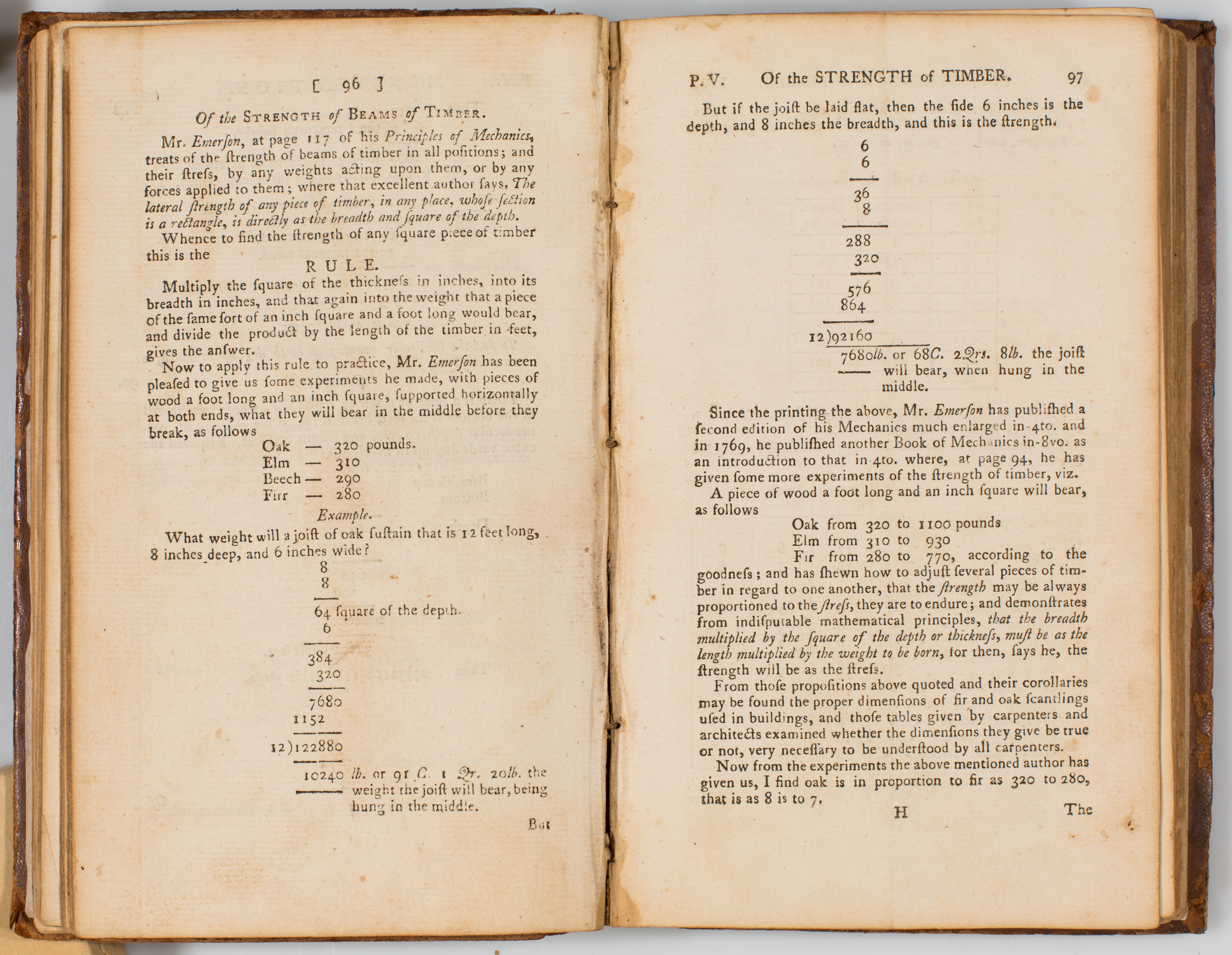
Francis Holliday (1717-1787), An Easy Introduction to Fortification and Practical Gunnery (London, 1774). Book Division, F2 1774 Ho.
Construction of most fortifications involved the use of timber for walls, platforms, bridges, and buildings. Francis Holliday’s practical manual includes, in addition to lessons in geometry, physics, and trigonometry, instructions for determining the strength of timber.

Elias Walker Durnford (fl. 1770-1794), “Plan and Section of a proposed Powder Magazine to contain 500 Barrels.” Pen and ink, [1767]. Thomas Gage papers. Map Division, Small Maps 1767.
The safe and efficient storage of black gunpowder required specially designed masonry buildings that would lessen the danger of accidental explosions and minimize damage to the powder by dampness. Elias Durnford’s plan includes details of racks for powder barrels. The design appears likely to have been based on those published in some contemporary manuals of fortification.
Exact Plan of General Gage’s Lines on Boston Neck in America (London, [1776]). Copperplate engraving. Map Division, M-208. Small Maps 1776.
The bustling seaport of Boston was protected only by Castle William, a fort on an island in the harbor. Rebellion in Massachusetts in 1775 posed a threat from the land side for the city’s British garrison. Boston’s position on a peninsula made it sufficient to fortify only the narrow neck that connected the town to the mainland. This was accomplished with a sort of modified hornwork and supporting defensive features.
This plan, copied for the Hibernian Magazine from an earlier version in an American periodical, shows the Boston Neck fortifications following the British evacuation of the city in March 1776.

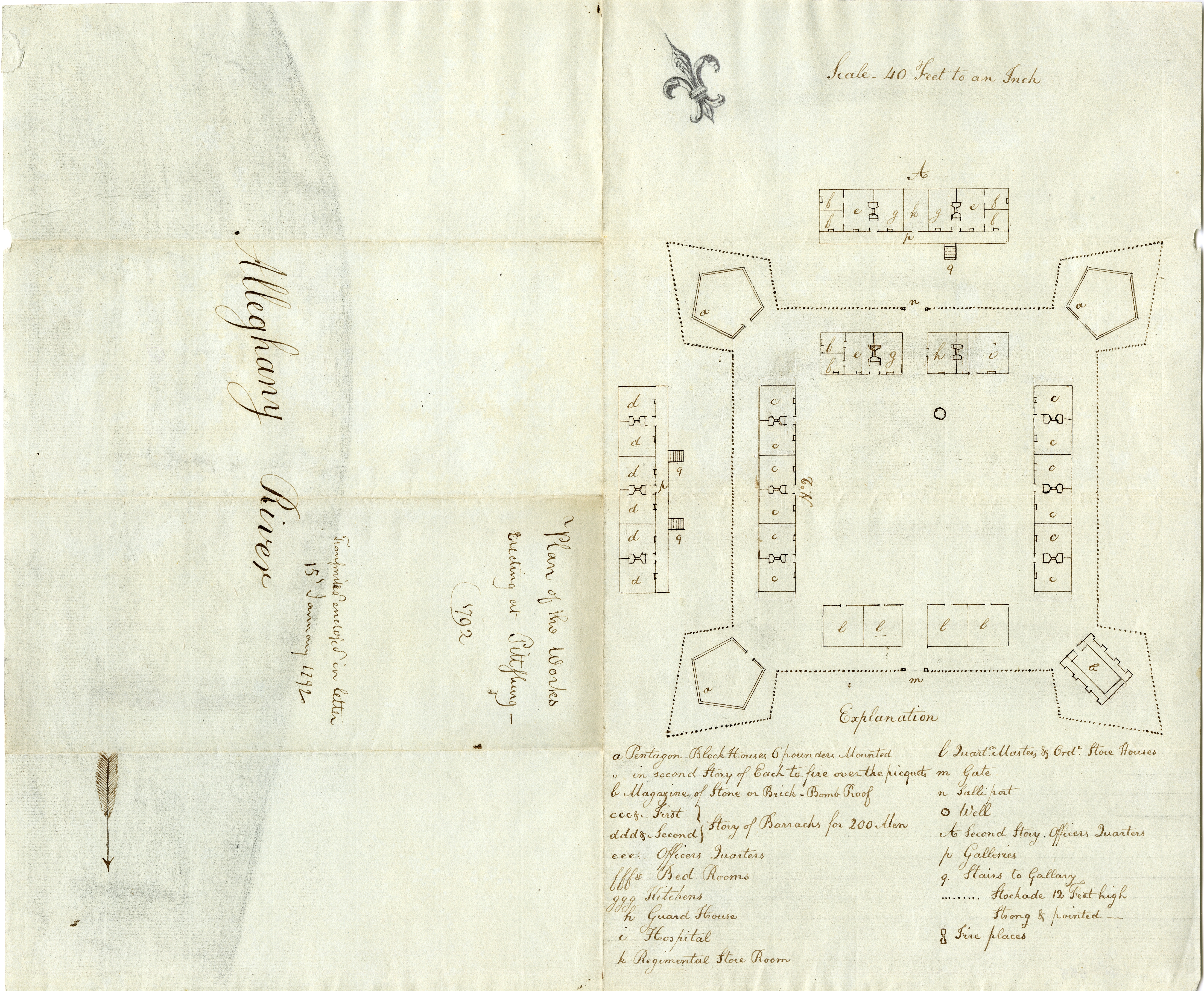
Isaac Craig (1742?-1826), “Plan of the Works Erecting at Pittsburg – 1792.” Pen and ink. Map Division, M-355. Small Maps 1792.
The U.S. successor to Fort Duquesne and Fort Pitt was a square stockade with four bastions, three of which each enclosed a pentagonal blockhouse. A powder magazine occupied the fourth bastion. Later known as Fort Lafayette or Fayette, the post served largely as a depot supporting U.S. Army operations in Ohio.
Drawn at the time of construction, this plan shows the fortifications and quarters in extraordinary detail.
Edward Spear, “Plan of the Blockhouse at the Falls of the Great Beaver.” Pen and ink, [1788]. Josiah Harmar Papers. Map Division, Small Maps 1788.
Lieutenant Spear’s drawing depicts the classic American blockhouse form: a two-story log building pierced by loopholes for muskets and ports for cannon. The overhung second story had openings in its floor through which defenders could fire down to flank the ground floor walls. Although blockhouses were frequently elements of larger forts, many, including this example from Pennsylvania, were intended to stand alone.


Theodosius McDonald, “A Plan of Fort Ligonier . . . February 8th Annoque Domini 1760.” Pencil, pen and ink. Map Division, M-1319. Small Maps 1760.
Fort Ligonier was constructed in 1758 to support the advance of Colonel John Forbes against French-held Fort Duquesne. McDonald’s plan depicts the fort and its outworks within its topographical setting on Loyalhanna Creek. The author provided details of the fort and troops as they were in 1758.
John Jacob Ulrich Rivardi, [Plan of Fort Lernoult and the town of Detroit].Watercolor, pen and ink, 1799. Map Division, M-125. Maps 6-N-14.
Although situated deep within the interior of North America, Detroit possessed rudimentary elements of a European fortress town. The civilian area was enclosed by a stockade wall and the town had a citadel in the form of Fort Lernoult with its ditch and four demi-bastions.
Major Rivardi captured the appearance of Detroit as it was at the time its British garrison peacefully relinquished the post to United States authorities in 1796.


[Siege of Charleston, South Carolina, 1780]. Pen and ink. Henry Clinton Papers. Map Division. Small Clinton Maps 271.
British General Sir Henry Clinton’s 1780 siege of Charleston went on for more than six weeks before its American garrison finally capitulated. This rough sketch map shows how the British dug their zigzag “saps” or “approaches” down both sides of the peninsula toward the fortified city (bottom). The assault on Charleston included two separate lines of “parallels” (parallel to the city’s defenses) in which troops could be sheltered to support the sappers and batteries of cannon.
The besiegers’ camp is at top with individual military units identified. The British position is protected against attack from the countryside by a line of redoubts.
Edward Barron, “Plan of the Fort of Annapolis Nova Scotia in its Present State 1779.” Watercolor, pen and ink. Henry Clinton Papers, no. 15. Map Division, Maps 4-D-5.
Barron intended to graphically depict the true condition of this earthen fort, which he did by realistically drawing the crumbling and eroding walls and outworks. A complex of garrison support buildings and quarters is located between the British fort and the village of Annapolis.

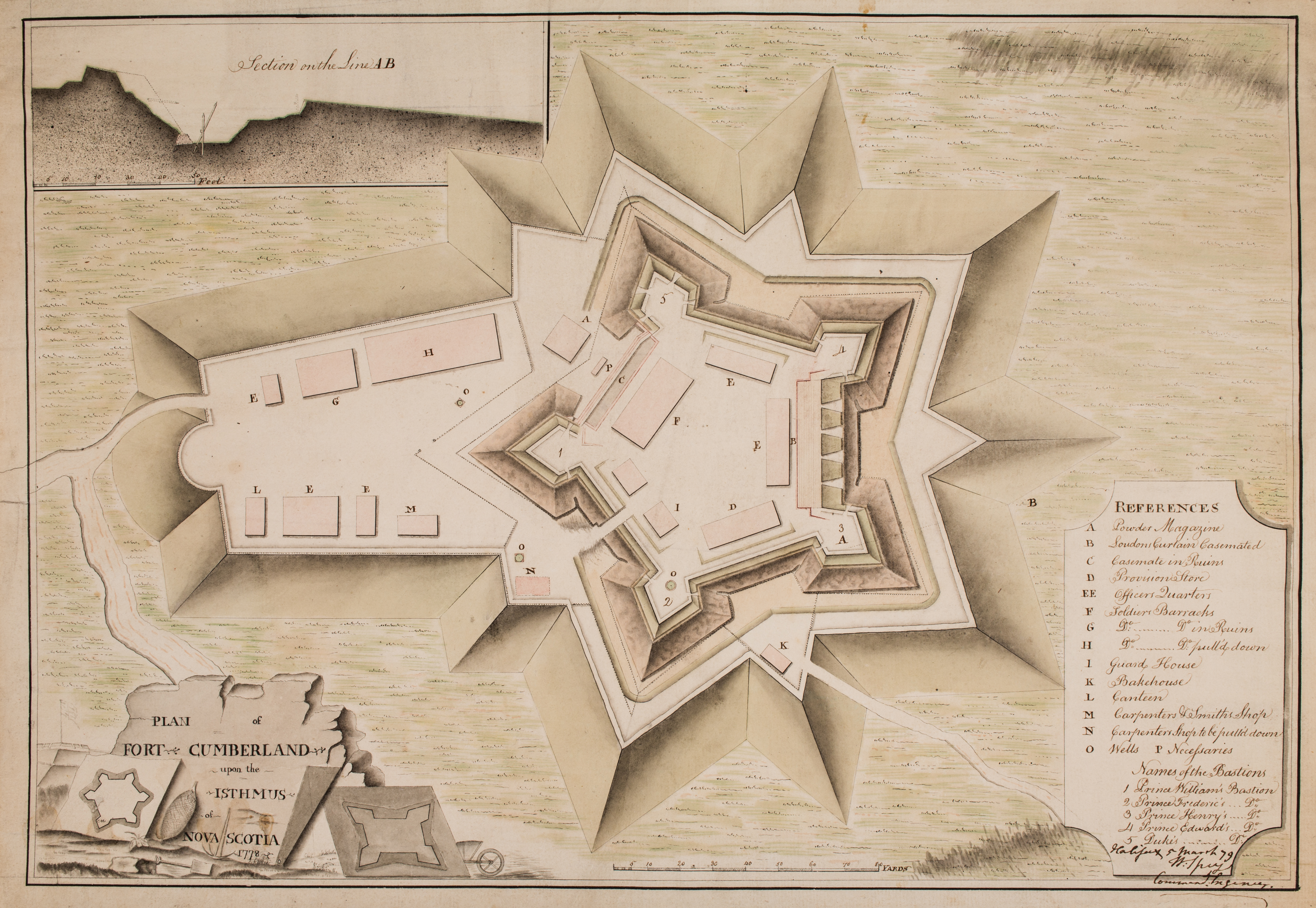
Charles Mist, “Plan of Fort Cumberland upon the Isthmus of Nova Scotia 1778.” Watercolor, pen and ink, 1779. Henry Clinton Papers, no. 13. Map Division, Maps 4-C-32.
Engineer Mist followed the normal conventions for the use of color when he recorded this earthen fort with its sod-faced walls. Here the garrison support buildings are protected within an extension of Fort Cumberland’s outworks. A detailed cross section suggests the general dilapidation of the fortifications.
Most intriguing is the title cartouche at lower left. It contains the author’s initials within a bastion of a hexagonal fortress. The design is further embellished with some of the tools of fort construction: a spade, a pickaxe, a wheelbarrow, a ruler, and a ball of twine for laying out a fort on the ground.
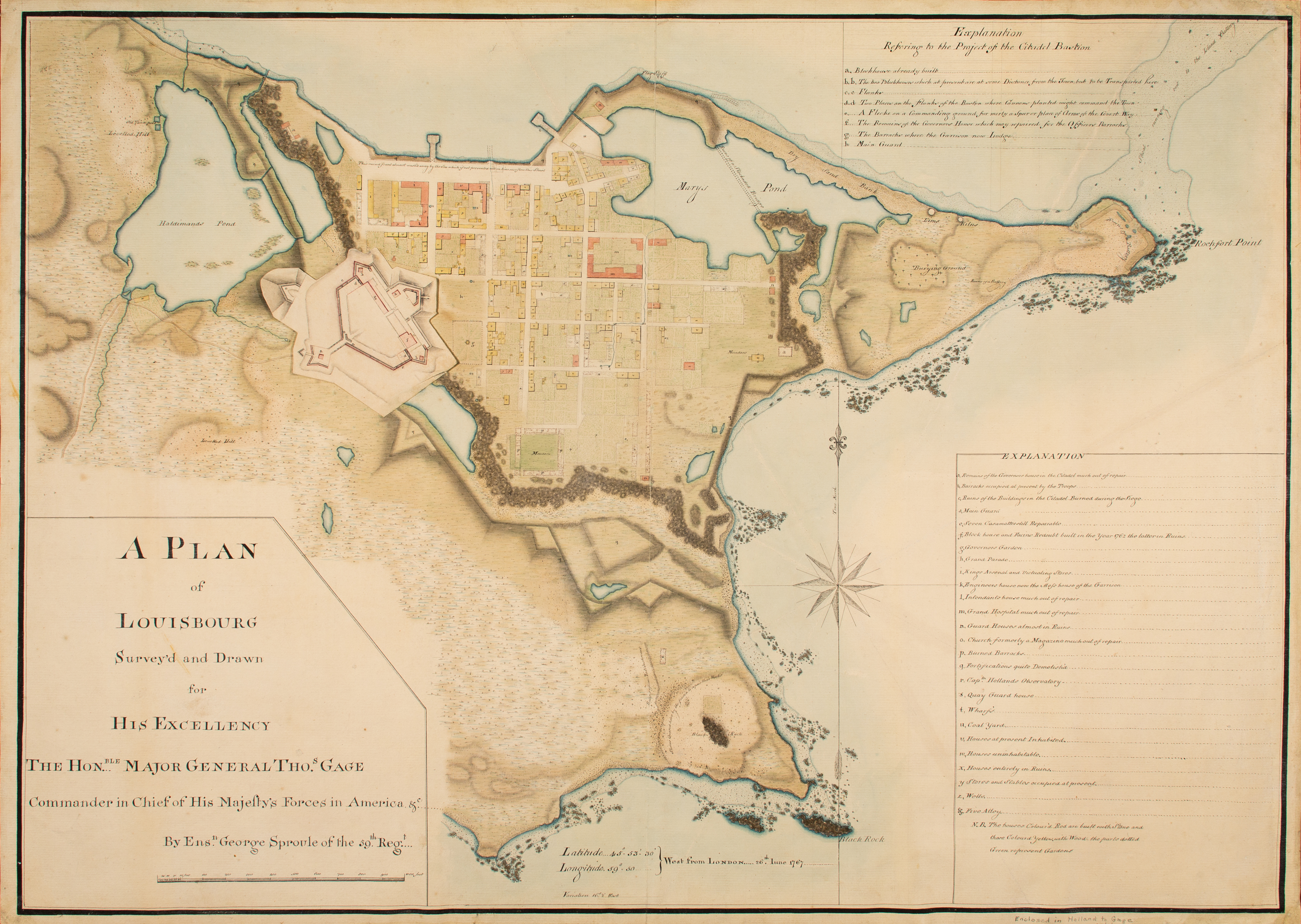
John Henry Bastide, “A Plan of Louisbourg. Intended only to shew by strong red the publick buildings lately erected, and by the faint red such as have had a thorough repair.” Watercolor, pen and ink, [1745-1748]. Peter Warren Papers. Map Division, Maps 4-B-16.
Bastide’s plan of Louisbourg dates to sometime during the three years between 1745 and 1748, when the town was occupied by New England soldiers. The place had been badly damaged during the siege of 1745, and this plan identifies structures that had been repaired. As a sign that Louisbourg was at least temporarily a part of the British Empire, the bastions have been renamed for British and allied royal figures.
This plan is particularly faithful to the coloring conventions of 18th-century fortification plans: carmine for masonry; burnt umber for dry ditches; green for turf; and blue or verdigris for water.

Special thanks are due to several members of the Clements Library staff, who assisted in the mounting and digitizing of this exhibit. Preparation of the physical exhibit was the responsibility of Julie Fremuth, whose steady and artistic eye gave depth and color to the surroundings of the plans on display. Terese M. Austin proofread labels, and Diana Sykes scanned the smaller plans. Austin Thomason of Michigan Photo Services photographed larger items, and Clayton Lewis captured images of the individual cases. Pulling it all together was the job of Kari Tant, who admirably succeeded in creating a handsome addition to the Clements Library website. Thanks to you all.