Case 9
Case 9: Laying Out a Fort
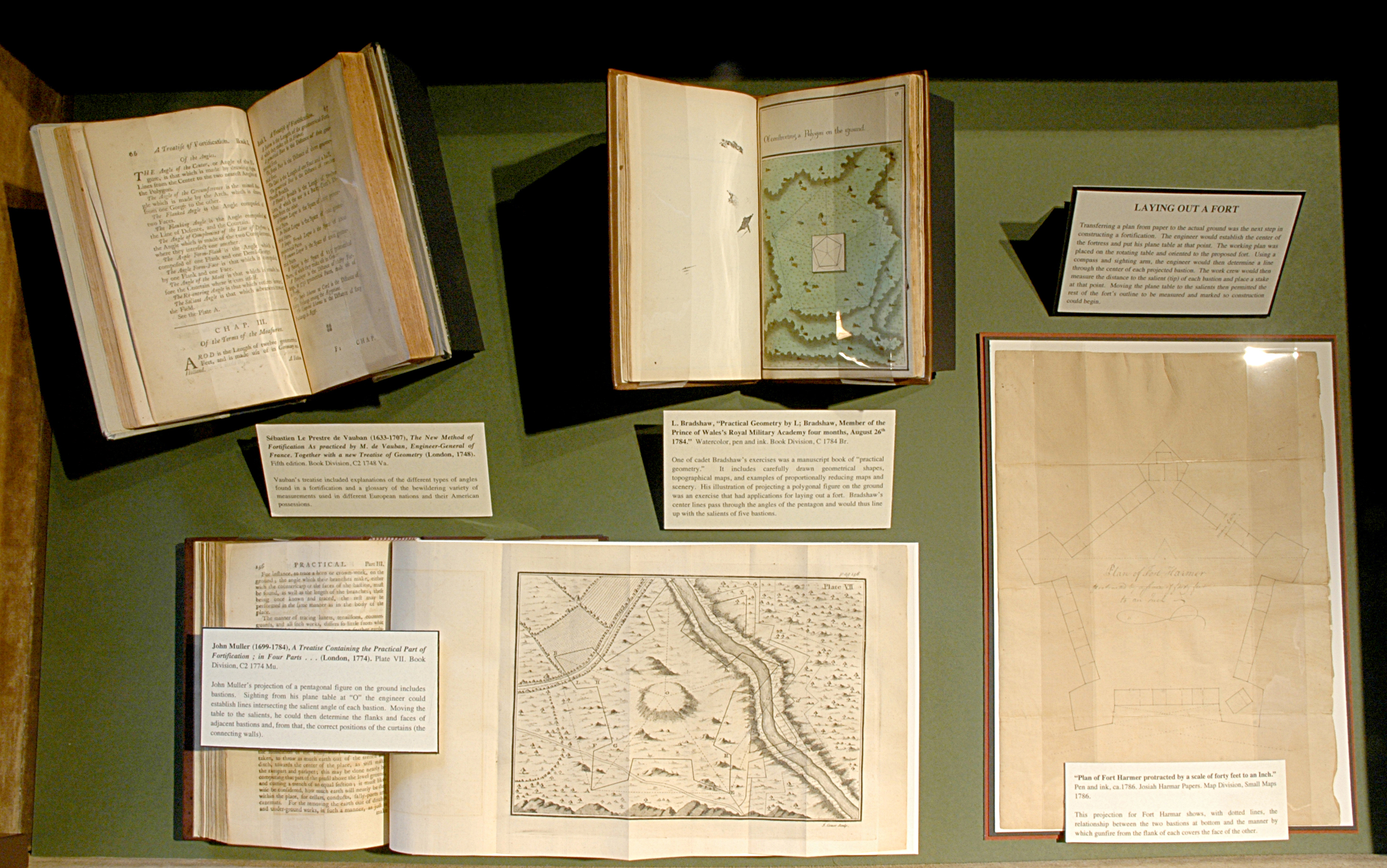
Transferring a plan from paper to the actual ground was the next step in constructing a fortification. The engineer would establish the center of the fortress and put his plane table at that point. The working plan was placed on the rotating table and oriented to the proposed fort. Using a compass and sighting arm, the engineer would then determine a line through the center of each projected bastion. The work crew would then measure the distance to the salient (tip) of each bastion and place a stake at that point. Moving the plane table to the salients then permitted the rest of the fort’s outline to be measured and marked so construction could begin.
L. Bradshaw, “Practical Geometry by L; Bradshaw, Member of the Prince of Wales’s Royal Military Academy four months, August 26th 1784.” Watercolor, pen and ink. Book Division, C 1784 Br.
One of cadet Bradshaw’s exercises was a manuscript book of “practical geometry.” It includes carefully drawn geometrical shapes, topographical maps, and examples of proportionally reducing maps and scenery. His illustration of projecting a polygonal figure on the ground was an exercise that had applications for laying out a fort. Bradshaw’s center lines pass through the angles of the pentagon and would thus line up with the salients of five bastions.
“Plan of Fort Harmer protracted by a scale of forty feet to an Inch.” Pen and ink, ca.1786. Josiah Harmar Papers. Map Division, Small Maps 1786.
This projection for Fort Harmar shows, with dotted lines, the relationship between the two bastions at bottom and the manner by which gunfire from the flank of each covers the face of the other.
Sébastien Le Prestre de Vauban (1633-1707), The New Method of Fortification As practiced by M. de Vauban, Engineer-General of France. Together with a new Treatise of Geometry (London, 1748). Fifth edition. Book Division, C2 1748 Va.
Vauban’s treatise included explanations of the different types of angles found in a fortification and a glossary of the bewildering variety of measurements used in different European nations and their American possessions.
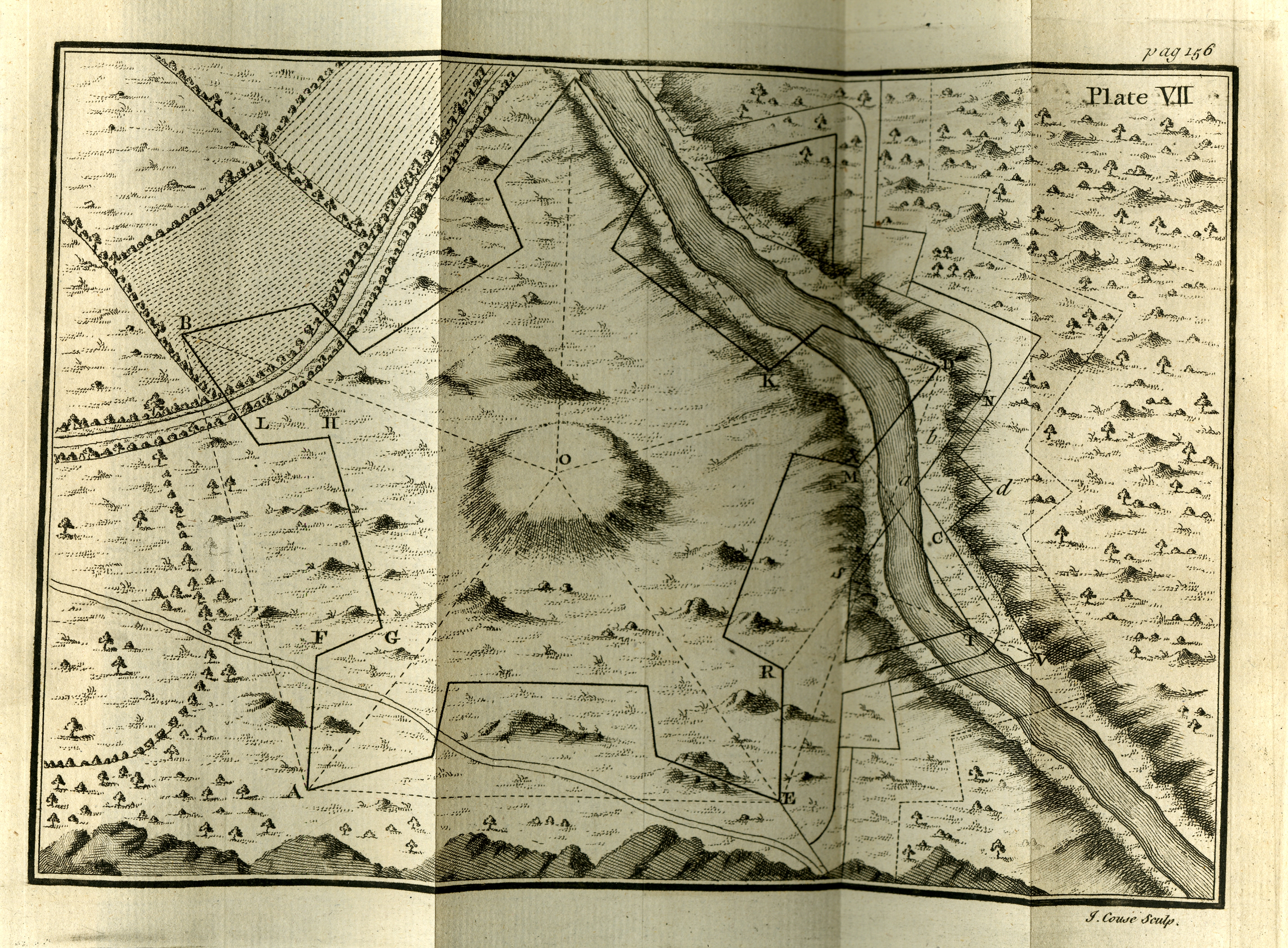
John Muller (1699-1784), A Treatise Containing the Practical Part of Fortification ; in Four Parts . . . (London, 1774). Plate VII. Book Division, C2 1774 Mu.
John Muller’s projection of a pentagonal figure on the ground includes bastions. Sighting from his plane table at “O” the engineer could establish lines intersecting the salient angle of each bastion. Moving the table to the salients, he could then determine the flanks and faces of adjacent bastions and, from that, the correct positions of the curtains (the connecting walls).


